Power Brake Booster Schematic . If your ratio is around 6:1 you are getting too much mechanical advantage making the. The brake booster mounts on the firewall of the vehicle and is connected to the brake pedal with a rod inside the cabin. the brake booster vacuum pump diagram is a visual representation of the various components that make up the brake booster vacuum pump system. understanding the vacuum brake booster: This system is responsible for generating the vacuum needed to assist in braking, providing extra power to the brake pedal for easier and more efficient braking. power brakes will require a 4:1 to 5:1 ratio. Detailed procedure, materials and tools for. The most common way to provide power braking is with a vacuum brake booster.
from detoxicrecenze.com
The most common way to provide power braking is with a vacuum brake booster. If your ratio is around 6:1 you are getting too much mechanical advantage making the. power brakes will require a 4:1 to 5:1 ratio. Detailed procedure, materials and tools for. This system is responsible for generating the vacuum needed to assist in braking, providing extra power to the brake pedal for easier and more efficient braking. understanding the vacuum brake booster: The brake booster mounts on the firewall of the vehicle and is connected to the brake pedal with a rod inside the cabin. the brake booster vacuum pump diagram is a visual representation of the various components that make up the brake booster vacuum pump system.
Power Brake Booster Diagram My Wiring DIagram
Power Brake Booster Schematic the brake booster vacuum pump diagram is a visual representation of the various components that make up the brake booster vacuum pump system. power brakes will require a 4:1 to 5:1 ratio. If your ratio is around 6:1 you are getting too much mechanical advantage making the. The brake booster mounts on the firewall of the vehicle and is connected to the brake pedal with a rod inside the cabin. This system is responsible for generating the vacuum needed to assist in braking, providing extra power to the brake pedal for easier and more efficient braking. the brake booster vacuum pump diagram is a visual representation of the various components that make up the brake booster vacuum pump system. The most common way to provide power braking is with a vacuum brake booster. Detailed procedure, materials and tools for. understanding the vacuum brake booster:
From www.autozone.com
Repair Guides Brake Operating System Power Brake Booster Power Brake Booster Schematic This system is responsible for generating the vacuum needed to assist in braking, providing extra power to the brake pedal for easier and more efficient braking. If your ratio is around 6:1 you are getting too much mechanical advantage making the. understanding the vacuum brake booster: the brake booster vacuum pump diagram is a visual representation of the. Power Brake Booster Schematic.
From detoxicrecenze.com
Power Brake Booster Diagram My Wiring DIagram Power Brake Booster Schematic The brake booster mounts on the firewall of the vehicle and is connected to the brake pedal with a rod inside the cabin. power brakes will require a 4:1 to 5:1 ratio. the brake booster vacuum pump diagram is a visual representation of the various components that make up the brake booster vacuum pump system. Detailed procedure, materials. Power Brake Booster Schematic.
From enginedatapunchers.z21.web.core.windows.net
Power Brake System Diagram Power Brake Booster Schematic understanding the vacuum brake booster: power brakes will require a 4:1 to 5:1 ratio. The most common way to provide power braking is with a vacuum brake booster. Detailed procedure, materials and tools for. This system is responsible for generating the vacuum needed to assist in braking, providing extra power to the brake pedal for easier and more. Power Brake Booster Schematic.
From studyschoolexultance.z21.web.core.windows.net
Hydro Boost Power Brake Booster Kit Power Brake Booster Schematic The most common way to provide power braking is with a vacuum brake booster. If your ratio is around 6:1 you are getting too much mechanical advantage making the. understanding the vacuum brake booster: power brakes will require a 4:1 to 5:1 ratio. Detailed procedure, materials and tools for. the brake booster vacuum pump diagram is a. Power Brake Booster Schematic.
From www.justanswer.com
Buick Brake Booster Replacement StepbyStep Guide JustAnswer Power Brake Booster Schematic The brake booster mounts on the firewall of the vehicle and is connected to the brake pedal with a rod inside the cabin. understanding the vacuum brake booster: This system is responsible for generating the vacuum needed to assist in braking, providing extra power to the brake pedal for easier and more efficient braking. power brakes will require. Power Brake Booster Schematic.
From mavink.com
Chevy Brake Booster Diagram Power Brake Booster Schematic This system is responsible for generating the vacuum needed to assist in braking, providing extra power to the brake pedal for easier and more efficient braking. understanding the vacuum brake booster: the brake booster vacuum pump diagram is a visual representation of the various components that make up the brake booster vacuum pump system. The most common way. Power Brake Booster Schematic.
From www.autozone.com
Repair Guides Brake Operating System Power Brake Boosters Power Brake Booster Schematic If your ratio is around 6:1 you are getting too much mechanical advantage making the. understanding the vacuum brake booster: The brake booster mounts on the firewall of the vehicle and is connected to the brake pedal with a rod inside the cabin. The most common way to provide power braking is with a vacuum brake booster. This system. Power Brake Booster Schematic.
From gmclassics.com
Power Brake Kit 9″ Booster for 19621967 Nova GM Classics Power Brake Booster Schematic Detailed procedure, materials and tools for. power brakes will require a 4:1 to 5:1 ratio. If your ratio is around 6:1 you are getting too much mechanical advantage making the. understanding the vacuum brake booster: This system is responsible for generating the vacuum needed to assist in braking, providing extra power to the brake pedal for easier and. Power Brake Booster Schematic.
From repairfixcraftiest.z22.web.core.windows.net
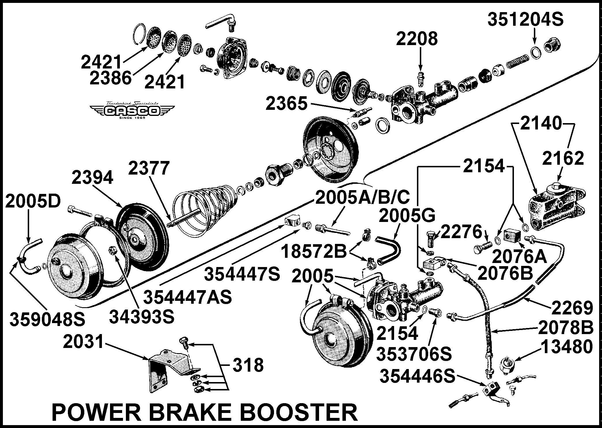
Power Brake Booster Parts Power Brake Booster Schematic understanding the vacuum brake booster: The brake booster mounts on the firewall of the vehicle and is connected to the brake pedal with a rod inside the cabin. the brake booster vacuum pump diagram is a visual representation of the various components that make up the brake booster vacuum pump system. This system is responsible for generating the. Power Brake Booster Schematic.
From www.autozone.com
Repair Guides Brake Operating System Power Brake Booster Power Brake Booster Schematic The brake booster mounts on the firewall of the vehicle and is connected to the brake pedal with a rod inside the cabin. If your ratio is around 6:1 you are getting too much mechanical advantage making the. power brakes will require a 4:1 to 5:1 ratio. the brake booster vacuum pump diagram is a visual representation of. Power Brake Booster Schematic.
From www.autozone.com
Repair Guides Brake Operating System Power Brake Booster Power Brake Booster Schematic power brakes will require a 4:1 to 5:1 ratio. This system is responsible for generating the vacuum needed to assist in braking, providing extra power to the brake pedal for easier and more efficient braking. The most common way to provide power braking is with a vacuum brake booster. the brake booster vacuum pump diagram is a visual. Power Brake Booster Schematic.
From mungfali.com
Brake Power Booster Cutaway Diagram Power Brake Booster Schematic The brake booster mounts on the firewall of the vehicle and is connected to the brake pedal with a rod inside the cabin. Detailed procedure, materials and tools for. If your ratio is around 6:1 you are getting too much mechanical advantage making the. the brake booster vacuum pump diagram is a visual representation of the various components that. Power Brake Booster Schematic.
From www.autozone.com
Repair Guides Hydraulic Braking System Power Booster Power Brake Booster Schematic power brakes will require a 4:1 to 5:1 ratio. Detailed procedure, materials and tools for. If your ratio is around 6:1 you are getting too much mechanical advantage making the. the brake booster vacuum pump diagram is a visual representation of the various components that make up the brake booster vacuum pump system. The most common way to. Power Brake Booster Schematic.
From www.autozone.com
Repair Guides Brake Operating System Power Brake Booster Power Brake Booster Schematic the brake booster vacuum pump diagram is a visual representation of the various components that make up the brake booster vacuum pump system. understanding the vacuum brake booster: This system is responsible for generating the vacuum needed to assist in braking, providing extra power to the brake pedal for easier and more efficient braking. power brakes will. Power Brake Booster Schematic.
From www.autozone.com
Repair Guides Brake Operating Systems Power Brake Boosters Power Brake Booster Schematic The most common way to provide power braking is with a vacuum brake booster. understanding the vacuum brake booster: The brake booster mounts on the firewall of the vehicle and is connected to the brake pedal with a rod inside the cabin. This system is responsible for generating the vacuum needed to assist in braking, providing extra power to. Power Brake Booster Schematic.
From diagramlibraryvic.z5.web.core.windows.net
Vacuum Booster For Power Brakes Power Brake Booster Schematic Detailed procedure, materials and tools for. If your ratio is around 6:1 you are getting too much mechanical advantage making the. The brake booster mounts on the firewall of the vehicle and is connected to the brake pedal with a rod inside the cabin. understanding the vacuum brake booster: the brake booster vacuum pump diagram is a visual. Power Brake Booster Schematic.
From diagramdataconley.z5.web.core.windows.net
Hydro Boost Brake System Diagram Power Brake Booster Schematic Detailed procedure, materials and tools for. understanding the vacuum brake booster: The brake booster mounts on the firewall of the vehicle and is connected to the brake pedal with a rod inside the cabin. The most common way to provide power braking is with a vacuum brake booster. If your ratio is around 6:1 you are getting too much. Power Brake Booster Schematic.
From www.autozone.com
Repair Guides Brake System Power Brake Booster Power Brake Booster Schematic This system is responsible for generating the vacuum needed to assist in braking, providing extra power to the brake pedal for easier and more efficient braking. The brake booster mounts on the firewall of the vehicle and is connected to the brake pedal with a rod inside the cabin. power brakes will require a 4:1 to 5:1 ratio. . Power Brake Booster Schematic.